The filler in the printed chassis and pushing block (in holes and on sides) is removed using a screw driver or spatula.
A linear ball bearing bushing is inserted into the side holes on the pushing block. They should fit tightly so a little force may be needed to insert them.
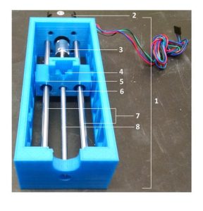
Insert the ¼” nut up through the slot in the bottom of the pushing block.
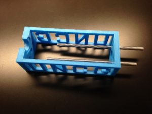
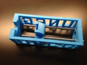
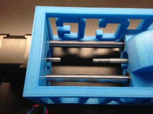
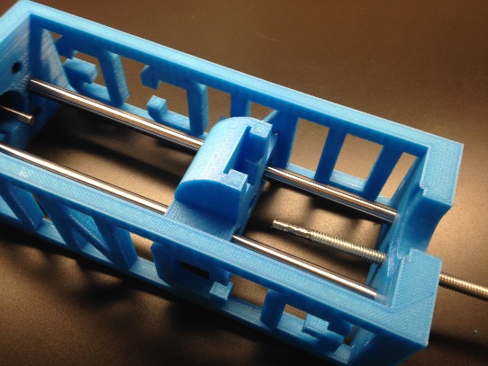
The smooth support rods are pushed through the two side holes next to the large hole in the chassis. The smooth rods are then fed through the ball bearing bushings assembled in the previous step. Assure that the pushing block is pointing towards the opening in the chassis where the syringe will be placed before pushing the support rods completely in. The fit is snug and should be flush when placing the motor on the chassis.
Secure the motor in place with 4 flat socket screws (M3, 0.5 x 14 mm).
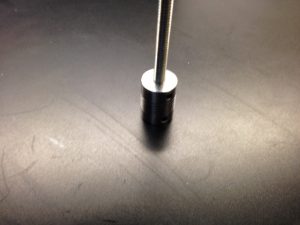
A fully threaded ¼”-20 bolt will need to be cut to be approximately 7.1 inches long for the pump chassis. A 2 foot long rod can then be used to generate 3 rods for 3 syringe pumps.
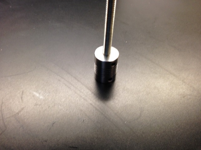
Once the bolt has been cut, it will have to be grinded down to fit into the coupler (approximately 5 mm in diameter). A Dremel tool is suggested although a metal file is also suitable. Check to make sure the modified bolt fits into the coupler, but do not tighten the screws to attach the two pieces.
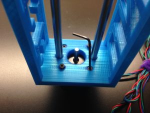
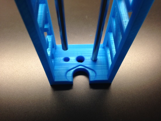
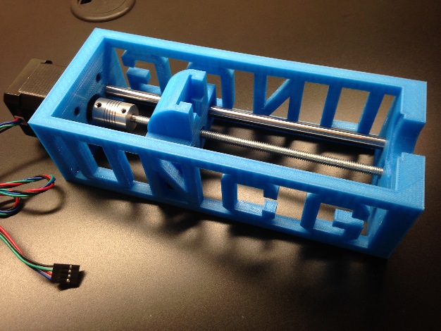
Take the modified bolt, pass the modified end through the large center hole of the chassis and then thread it through the nut in the pushing block. Make sure to have the end that was ground down to 5 mm in diameter pointing towards the motor.
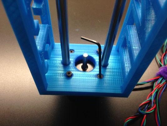
Once the modified end is a couple inches past the pushing block, attach the linear coupler to the bolt and tighten. Then attach the other end of the coupler to the stepper motor and tighten.
All parts should fit tightly and screws can be torqued down. You are now ready to connect your syringe pump to the electronics.