

Designing and Connecting the Tubing
If you are using this as a simple syringe pump, you clearly do not need to worry about this section. Just put the syringe in the syringe pump and away you go!
The tubing required for flow chemistry is dictated by the type of chemistry being studied. In this section we will be discussing the typical and simple setups that are available.
Tubing
The typical tubing for flow chemistry is typically PFA . This is flexible (but be careful not to kink it) and see-through so monitoring of the reactions is possible visually. We recommend using an outer diameter of 1/16 inch and an inner diameter of either 0.04 or 0.02 inches.
Unlike running a reaction in a flask, a reaction is flow is continuously reacting. To determine the reaction time, you need to know the tube diameter, the flow rate, and the tube length. Using these, you can determine the retention time, which correlates to the reaction time. This is only true if either a quench is included in the flow system or if the flow system is being added into a bulk quench at the end. Below is an spreadsheet that can be used to determine the retention time for a given flow rate, tube diameter, and tube length.
Tubing Connectors
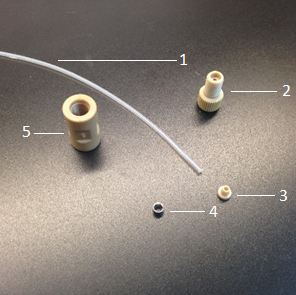
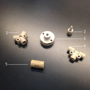
Components:
1. Tubing PFA 1/16” OD (0.02 or 0.04” ID) [Item #: 1507L or 1512L]
2. Nut PEEK 1/16” [LT-115X]
3. Ferrule SF [P-250X]
4. SS Ring 1/16” [included with P-250X]
5. Union P-702
Assembly
1. Place lock ring over PEEK ferrule; the flat face of ring faces away from ferrule.
2. Insert the ferrule/ring into the nut; flat face of ring lock fitted into ring at threaded end of the nut.
3. Insert tubing through the nut from opposite end of thread to include ring lock and ferrule; allow tubing to exit from ferrule such that the tubing is not flush with ferrule.
4. Use a union to thread onto nut; tighten the complex such that the tubing and ferrule are flush; ensure that tubing is outside of the ferrule prior to tightening.
5. Ferrule should be tightly bound around tubing; the nut may freely move along tubing length.

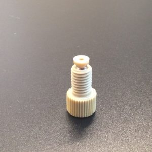
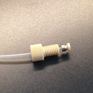
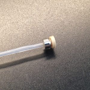
To connect the tubing to other parts of the system, you will need to attach a screw onto the end. Now you can screw the tubing into any type of compatible joint.
Joints
To have efficient mixing, use a T-joint. If you want two solutions to flow next to one another but not mix as quickly, use a Y-joint. Using the tubing connectors already assembled in the prior step, simply screw these into the T-joint or Y-joint. Finger tighten, but don’t strip the screws by tightening too hard.
Components:
- Y Assembly PEEK ¼-28 0.20” [P-512]
- Ferrule connector for tubing
- Manifold Assembly 7 Port 10-32 Std [P-170]
- Tee Assembly PEEK 1/16” 0.20” [P-712]
- Union
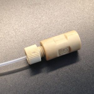
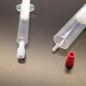
Syringe Connector
We recommend using a connector that uses a Leur lock for the syringe and screw system to link to the flow system. This enables a very tight and strong connection. We recommend part P-678 red or P-628 colorless.
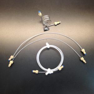
Heating/Cooling
To heat or cool the flow system, you can simply put the tubing into a hot/cold bath. The surface area to volume ratio is much better with flow than in flask, so heating and cooling is much more efficient. For convenience, we recommend using zip ties to bundle the tubing if using more than a few inches of tubing.
Additional Options
If you want to operate at higher pressures (e.g. above the boiling point of the solvent), you can utilize a back pressure regulator (Item #’s: P-786, P-791). Using other syringes will also help with the higher pressures.