Connecting the Electronics
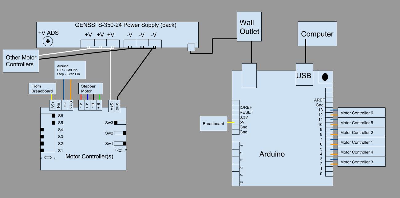
Below is a wire diagram for the entire system. This section is broken down into the pair-wise connections for each component involved.
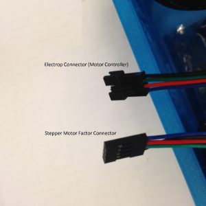
Stepper Motor to Motor Controller – The stepper motors typically come with 1 meter of cable. It is recommended to connect the stepper motor with the Electrop brand wire connectors since these typically have similar connectors and allow for quick disconnections between the syringe pumps and the rest of the electronics. This is helpful so that the system can be setup in a hood and then connecting to the electronics outside the hood. There are 4 wires coming from the stepper motors; A+ (blue), A- (red), B+ (green), B- (black). These will be connected to the motor controllers at the indicated slots.

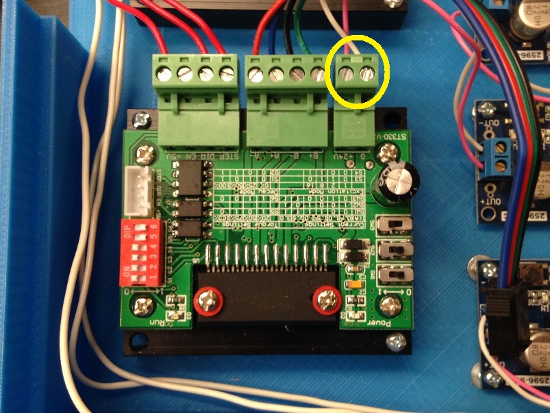
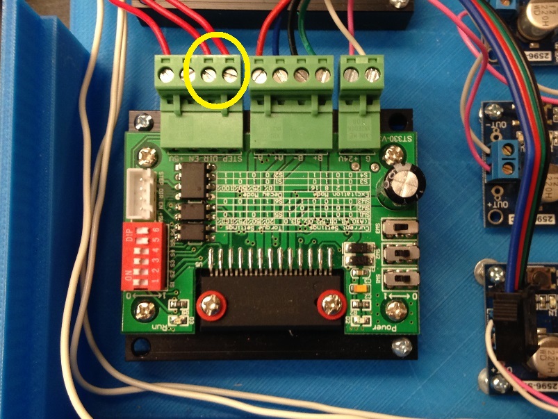
The connectors have frayed wires at the end, it is recommended to solder the ends of the Electrop connects to provide more durable connections. This will be the only time a soldering iron is needed. Connect to the motor controller at the correct position. Circled below is the connection to the stepper motor. Note: For all connections to the motor controller, loosen the screws shown below, insert the wire, and then tighten the screws to make the connection.
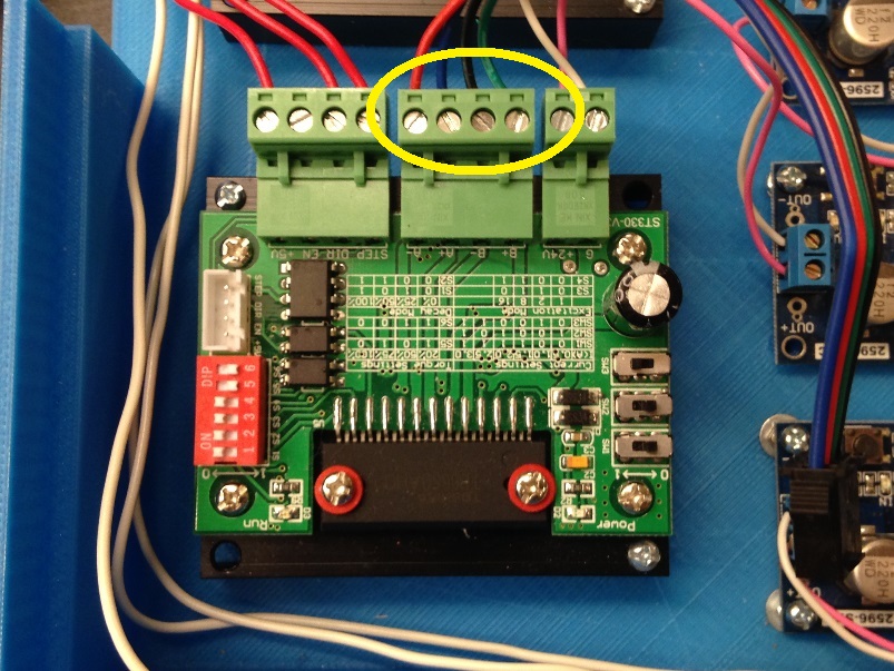
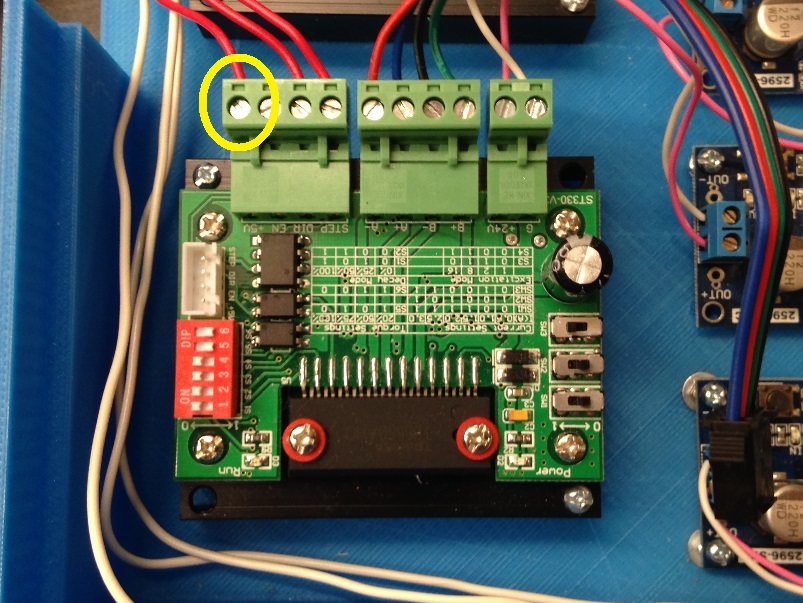
Power Supply Unit to Motor Controller – The PSU will have multiple +V and –V locations. Connect from any of the +V sites on the PSU to the +24V location on the motor controller and from any of the –V of the PSU to the Ground location on the motor controller. For the image below, the pink wires are the +V and the white wires are –V. Caution: The motor controllers can run on less than 24V. Higher than 32V, may cause damage without proper voltage regulators. Make sure that the power supply unit is not plugged in when doing this wiring.
Circled below are the wires from the power supply. This is labeled on the motor controller by +24V and G (ground).
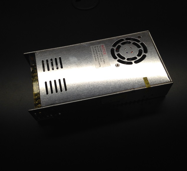
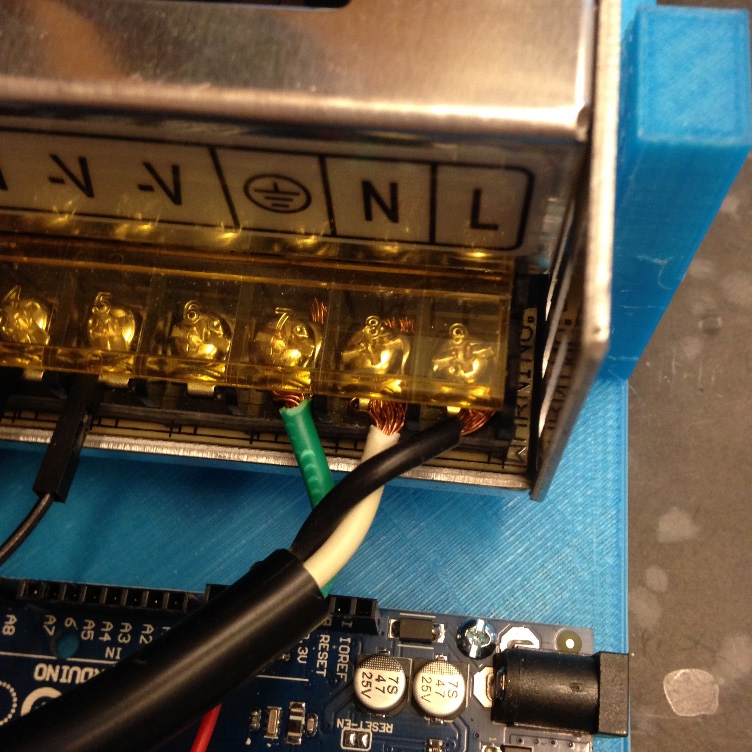
Power Supply Unit to Wall – As mentioned, many PSUs do not come with a wall plug. The plug wiring will depend on the PSU purchased, but a typical example is shown below. Green is ground, White is Neutral and Black in Line (power). DANGER: Verify the connections on the 3-prong cable before connecting.
Arduino to Motor Controller
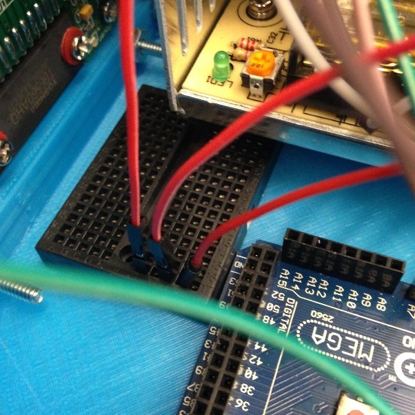
There are 3 wires connecting the Arduino to the motor controller, step, direction, and 5V wires. Since a single Arduino can power multiple syringe pumps it is beneficial to split the 5V line into multiple lines. We recommend doing this via a breadboard (described below). You will use jumper wires to directly connect the various positions on the Arduino to the motor controllers (e.g. 2 and 3 to syringe pump 1; 4 and 5 to syringe pump 2). Follow the wiring schematic to connect the positions to the motor controller but a key point is to have the odd numbered positions connecting to DIR and the even numbered positions connecting to STEP on the motor controllers. There are specific wiring connections from the Arduino (left circle) to the motor controller (right circle).
Motor Controller to Breadboard
The motor controller needs a 5V power supply from the Breadboard. This is simply a wire from the correct position in the breadboard into the 5V slot on the motor controller.

Arduino to Breadboard
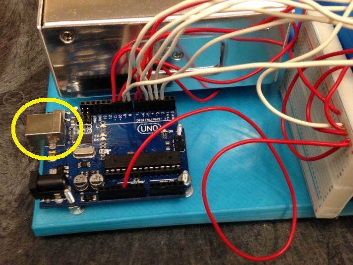
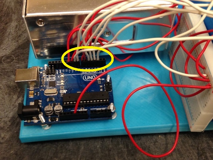
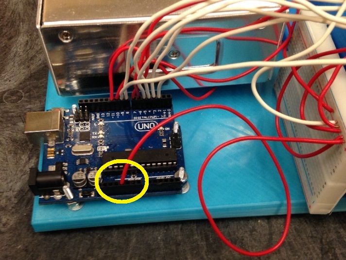
The 5V line from the Arduino needs to be split to all of the motor controllers. This is done via a Breadboard. Connect the Breadboard to the Arduino using a jumper wire, shown in the circle below. On the Breadboard, this will then make all of the wires in that row connected to the same 5V line. Any wire coming from this row of the Breadboard can now go to the motor controller’s 5V slot.
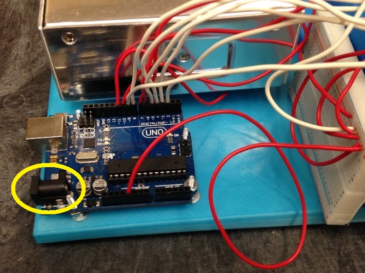
Arduino to Wall Outlet
Most Arduinos need to have a wall adapter purchased. This is not technically necessary since the Arduino can run on power from the USB connected to a computer. We recommend purchasing and using the additional plug for the Arduino to have standalone power. This simply plugs into the Arduino and then into the wall.
Arduino to Computer
The Arduino typically comes with a USB cord to communicate with a laptop. As mentioned, it can also be powered directly from the computer. Simply attach the cable to the Arduino and your computer.